
- HOW TO BUILD A USB PIC PROGRAMMER HOW TO
- HOW TO BUILD A USB PIC PROGRAMMER SERIAL
- HOW TO BUILD A USB PIC PROGRAMMER SOFTWARE
- HOW TO BUILD A USB PIC PROGRAMMER PC
HOW TO BUILD A USB PIC PROGRAMMER SOFTWARE
The answer is that you use a simple piece of software to load Program in the device to load and start my program! If you ask the question how can I load and start my program if there is no The process ofīooting (bootstrapping or starting a system) also seems like an impossible task To pull himself up by his boot straps an impossible task. Interestingly it is called a bootloader referring to a legend (starts up) and loads Hence the label: Bootloader. WhenĪll data has been loaded and programmed it starts up the new program or boots Program the rest of the FLASH memory i.e. When activated it accepts data from the Rx line using it to The bootloader is stored but you probably won't notice as there is a lot of You lose a small amount of programming memory that is where Use a bootloader and this allows immediate upload of a program using only a Within a set time period after reset e.g. It is a small program that typically monitors the USART receiveĭata line (RX) and activates itself if there is any activity on this line Now more common to expect this self-programming action rather than thinking of Parts of their own FLASH memory - these days that is loads of them and it is This method is only usable on the newer devices that can re-program Programing a pic device and this is using a piece of software called aīootloader. PGM line low with 10k (approx.) when first programming (with HVP). That are LVP capable are factory shipped with LVP enabled. Programming - normal ICSP programmer) if you have an HVP programmer. Note: You can only change from LVP to HVP (High Volt Theĭisadvantage is that you loose one pin which may be ok for larger 40 pinĭevices but probably not for 18 pin devices. Newer PIC devices - as it suggests you don't need the higher voltage. LVPĪ method called LVP (or Low Volt Programming) is available for Sent, and voila - the microcontroller is programmed ready for use.
HOW TO BUILD A USB PIC PROGRAMMER SERIAL
From there the programmer presents the signals to theĪfter all the data is sent, a serial configuration word is This is routed to your programmer through the correct interface Takes the hex file generated from your compiler translating it into a serialĭata stream.
HOW TO BUILD A USB PIC PROGRAMMER PC
Another pin controls the programming voltage (at MCLR) and two othersĪnother program running on the PC (the programming software) See later) - they generate a serial data stream using two signal lines clockĪnd data. I recommend that you use a pic programmerĪll pic programmers work the same way (except the bootloader. Make any ICSP connection to your development hardware as you can not connectĭevelopment ground to -8V! so you have to remove and insert the chip. Swing of >13V that can be regulated by a zener to about 13V. Negative voltage the serial port generates). So the programmer's ground reference (to the PIC chip) is -8V (or whatever That they reference the programmer's ground to the -ve serial output voltage.

Just want to connect the programmer to my dev board, leave the chip in place,

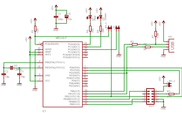
Useful for programming one off chips but you have to insert and remove theĬhip that you are programming moving from the programmer to the development Test the microcontroller program while the programmer is still attached.Ĭleverly uses the serial port to provide a high voltage programmer that does The programmer should isolate the microcontroller so you can High voltage programmer (but see bootloading). The serial port generates higher voltages and this fact is usedīy programmers such as a JDM pic programmers. Logic levels are nominally 5v so usually these programmers require use of anĮxternal power supply to generate the higher voltage. Voltages from the parallel port or USB port are not that high. The 13.5 volt level complicates the interface circuit since the The pin is (MCLR) 14V but on some newer PIC micros this is lowered to 13V so be Source : PIC application note ICSP (DS30277) To suitable logic levels for the microcontroller - most levels are ok as theyĪre, but for 'normal' (or high volt) programming of a pic microcontroller theįollowing voltage at the MCLR pin is needed: The pic programmer translates digital logic levels from the PC To the microcontroller and read it back for verification. Microcontroller using the PC's parallel,serial or USB port.
HOW TO BUILD A USB PIC PROGRAMMER HOW TO
Arduino Oversampling: How to Get More ADC Bits with No Extra Hardware!Ī pic programmer is a circuit which interfaces the PC to the.


 0 kommentar(er)
